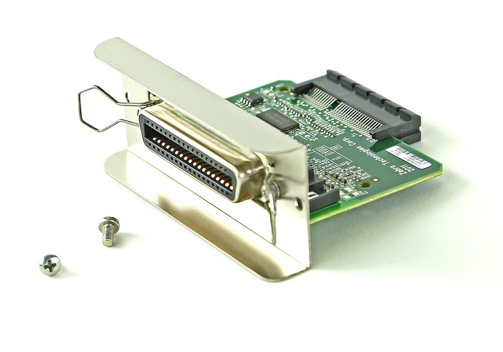

Given time, thus requiring minimal external circuitry to implement many simpler tasks. This port will allow the input of up to 9 bits or the output of 12 bits at any one The Parallel Port is the most commonly used port for interfacing home made projects.

#Parallel port pdf#
Once this processing is complete, the device will lower the Busy signal and may raise a brief ACK signal to indicate that it has finished.Introduction to Parallel Ports Hardware Properties Centronics? Port Addresses Software Registers - Standard Parallel Port (SPP) Bi-directional Ports Using the Parallel Port to Input 8 Bits Nibble Mode Using the Parallel Port's IRQ Parallel Port Modes in BIOS Parallel Port Modes and the ECP's Extended Control Register PDF Version The device will respond by raising its BUSY signal and then reading the data and performing some processing on it. This pulse informs the device that data is ready to be read. In Standard (or Compatibility) mode, data is sent to the connected device by writing the byte to the data port, then pulsing the STROBE signal. Relieving software of this requirement reduces CPU load and increases the port's maximum potential speed.įor a line printer, this method should be enough to get things going, simply sending characters using this method to the parallel port while the printer is online should get the print head moving, assuming no buffers are in the way to store the values.ĭepending on the connected device, you may have to raise the INITIALISE signal before data transmission to ready the device, and possibly again after in order to flush any buffers.

The more advanced types (or modes) of parallel ports, EPP and ECP, reduce this by providing hardware-based handshaking. This means that a standard mode has a maximum transfer rate of around 1000 bytes per second, depending on the timings of the computer and receiving device. This mode requires communuication handshaking to be performed by software which limits the maximum data throughput of the port. In Standard (or Compatibility) mode, data is sent using a mechanism called Centronics Handshaking, described below. In this mode, the Data register and the Control register are Write-Only and the Status register is Read-Only. Some BIOSes also support setting the default mode of the parallel port. All systems should support this mode and it may well be the default at boot time. This is the most basic of the parallel modes. This signal may result in a printer performing a reset and any buffers being flushed. INITIALISE, sometimes called PRIME, alerts the device that data that a data conversation is about to start. If this is set and the printer receives a Carriage-Return character (0x0D), the printer will automatically perform a Line-Feed (character 0x0A) as well. The STROBE signal is for handshaking and alerts the printer to data being ready at the data port.ĪUTO_LF is the Automatic Line-Feed signal. The INITIALISE signal is active low when writing to the IO port. The ERROR, ACK and BUSY signals are active low when reading from the IO port.

Their addresses are relative to the base address of the parallel port in question.Īny byte writen to this register is put on pins 2 through 9 of the port.Īny read from this register reflects the state of the port. You can help the wiki by accurately contributing to it.Įach parallel port has three IO port registers, Data, Status and Control. The BIOS Data Area should contain the IO base addresses of any existing parallel ports LPT1: 0x378 (or occasionally 0x3BC) (IRQ 7).Most parallel ports come in either 36 or 25 pin varieties.


 0 kommentar(er)
